

How To Fix Code C1241 Toyota
Diagnostic trouble lawmaking C1241 Land Cruiser
DESCRIPTION
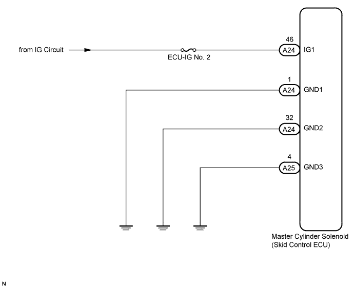
WIRING DIAGRAM
INSPECTION Procedure
Audit BATTERY
Audit ECU-IG NO. 2 FUSE
READ VALUE USING INTELLIGENT TESTER (IG1 VOLTAGE VALUE)
RECONFIRM DTC
Audit Sideslip Control ECU (IG1 Concluding)
INSPECT SKID Command ECU (GND Final)
RECONFIRM DTC
DTC C1241/41 Low Bombardment Positive Voltage
Description
If the voltage supplied to the IG1 final is within the DTC detection range due to malfunctions in components such equally the battery and alternator circuit, this DTC is stored.
| DTC Code | DTC Detection Status | Problem Area |
| C1241/41 | When either of the following conditions is detected: ane. Both of the following conditions continue for at least 10 seconds.
|
|
Wiring diagram
Inspection procedure
Detect:
When replacing the master cylinder solenoid, perform zero indicate calibration .
-
Check the battery voltage.
Standard voltage:
eleven to 14 Five
Result Result Go along to OK A NG 1GR-Fe B 2UZ-FE C 1VD-FTV D
| GO TO CHARGING SYSTEM (ON-VEHICLE INSPECTION) | |
| GO TO CHARGING SYSTEM (ON-VEHICLE INSPECTION) | |
| Go TO CHARGING SYSTEM (ON-VEHICLE INSPECTION) | |
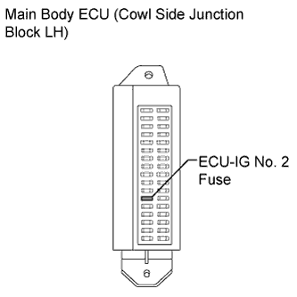
2.Audit ECU-IG NO. 2 FUSE
-
Remove the ECU-IG No. 2 fuse from the main body ECU (cowl side junction block LH).
-
Measure the resistance according to the value(south) in the tabular array below.
Standard Resistance:
Tester Connexion Condition Specified Condition ECU-IG No. two fuse Ever Below 1 ?
| REPLACE ECU-IG NO. 2 FUSE | |
3.READ VALUE USING INTELLIGENT TESTER (IG1 VOLTAGE VALUE)
-
Install the ECU-IG No. 2 fuse.
-
Connect the intelligent tester to the DLC3.
-
Turn the ignition switch to ON and turn the intelligent tester on.
-
Outset the engine.
-
Enter the following menus: Chassis / ABS/VSC/TRC / Data List.
ABS/VSC/TRC Tester Display Measurement Particular/Range Normal Condition Diagnostic Note IG1 Voltage Value IG1 voltage value/min.: 0 V, max.: 255 Five nine.5 to 14.0 V -
-
Measure the voltage output from the skid control ECU displayed on the intelligent tester.
OK:
The output voltage displayed on the intelligent tester is within 9.5 to xiv.0 V.
-
Clear the DTCs .
-
Check if the aforementioned DTCs are output .
HINT:
Reinstall the sensors, connectors, etc. and restore the previous vehicle atmospheric condition before rechecking for DTCs.
Event Outcome Proceed to DTC is output LHD A RHD B DTC is not output (When troubleshooting in accordance with the Diagnostic Trouble Code Chart) C DTC is non output (When troubleshooting in accordance with the Trouble Symptoms Table) D
| Supercede Principal CYLINDER SOLENOID | |
| USE SIMULATION METHOD TO CHECK | |
| Keep TO NEXT Excursion INSPECTION SHOWN IN Problem SYMPTOMS TABLE | |
| A | |
| Replace Master CYLINDER SOLENOID |
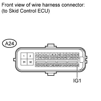
5.Audit Sideslip CONTROL ECU (IG1 TERMINAL)
-
Disconnect the A24 skid control ECU connector.
-
Measure the voltage according to the value(southward) in the table beneath.
Standard Voltage:
Tester Connexion Switch Status Specified Condition A24-46 (IG1) - Torso footing Ignition switch ON 11 to 14 V
| REPAIR OR REPLACE HARNESS OR CONNECTOR | |
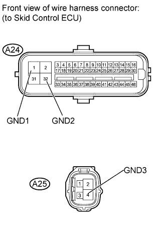
vi.INSPECT SKID Command ECU (GND Concluding)
-
Disconnect the A24 and A25 skid control ECU connectors.
-
Measure the resistance according to the value(s) in the table below.
Standard Resistance:
Tester Connection Condition Specified Status A24-1 (GND1) - Trunk ground Always Below 1 ? A24-32 (GND2) - Body ground Always Beneath 1 ? A25-iv (GND3) - Body ground Ever Below i ?
| REPAIR OR REPLACE HARNESS OR CONNECTOR | |
-
Clear the DTCs .
-
Check if the same DTCs are output .
HINT:
Reinstall the sensors, connectors, etc. and restore the previous vehicle conditions earlier rechecking for DTCs.
Result Result Go on to DTC is output LHD A RHD B DTC is not output (When troubleshooting in accordance with the Diagnostic Trouble Lawmaking Chart) C DTC is not output (When troubleshooting in accordance with the Trouble Symptoms Table) D
| Supervene upon MASTER CYLINDER SOLENOID | |
| Use SIMULATION METHOD TO CHECK | |
| PROCEED TO Side by side Circuit INSPECTION SHOWN IN Problem SYMPTOMS TABLE | |
| A | |
| Supersede MASTER CYLINDER SOLENOID |
Source: https://auto-master.su/en/toyota/land-cruiser/abc/c1241
0 Response to "How To Fix Code C1241 Toyota"
Post a Comment